Sharding Graph Data with Neo4j Fabric
This guide will discuss the concept of sharding graph data using Neo4j Fabric.
If you are not familiar with graph database concepts, please read the section on graph databases. It also helps to be familiar with the architecture of database clustering in Neo4j.
Beginner
Data sharding is a topic that has arisen from the vast quantities of data stored in databases of all types. It may be often-associated with document, key-value, or columnar NoSQL database types, but it has broadened its scope to include relational and graph databases, as well. We will discuss what data sharding is and why it is used, as well as what it looks like and how it operates for Neo4j.
What is data sharding?
Data sharding is dividing data into horizontal partitions that are organized into various instances or servers, most often to spread load across multiple access points. These shards can be accessed individually or aggregated to see all of the data, when required.
Why use sharding?
A few different use cases make sense to shard into separate databases or instances. Many of these have to do with business environments and data size. We can look at few listed here.
-
For legal or privacy reasons, you need to store some data in isolated databases to protect or limit access (i.e. GDPR laws).
-
Data is already siloed into separate instances for everyday business, but you might need to weave them together into a unified graph (i.e. knowledge graph).
-
To minimize latency of queries in various regions, relevant segments of the graph can be stored in cloud regions close to query request sources (i.e. application hosted in Europe that queries for data stored in a Europe cloud region).
-
Archived data might be separated by date, such as by year, but adhoc reporting or other needs might require queries across these graphs.
-
The graph size is becoming large enough (tens of billions of nodes) that it makes sense to divide the data into smaller graphs to run on smaller-sized hardware and be accessed by necessary parties.
There are other possible scenarios where sharding the data may be the solution of choice, but at the core, sharding provides a way to distribute data across instances or geographic regions for easier or more secure access.
Sharding Example
For instance, let us say we have people data stored in our system. This could be for customers, social network profiles, or any use case requiring storage of person data. We might have millions or billions of people in our system, and we want to divide this up to make querying easier for users.
Here is our data as rows and columns (typical relational database structure). However, we could format this data as individual documents, entities, or any other database structure.
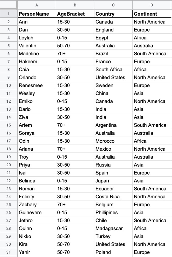
This is a very small sample of the data in our system, but we can choose to shard it in a few different ways.
-
Separate by continent - this would divide the records into 6 different segments (Africa, Asia, Australia, Europe, North America, South America).
-
Separate by age bracket - this would divide the records into 5 segments (0-15 years old, 15-30 years old, 30-50 years old, 50-70 years old, 70+ years old).
-
Other - based on any other data we might collect, such as job role, year of system entry, residency status, relationships to other nodes, etc.
The first two options are shown below.
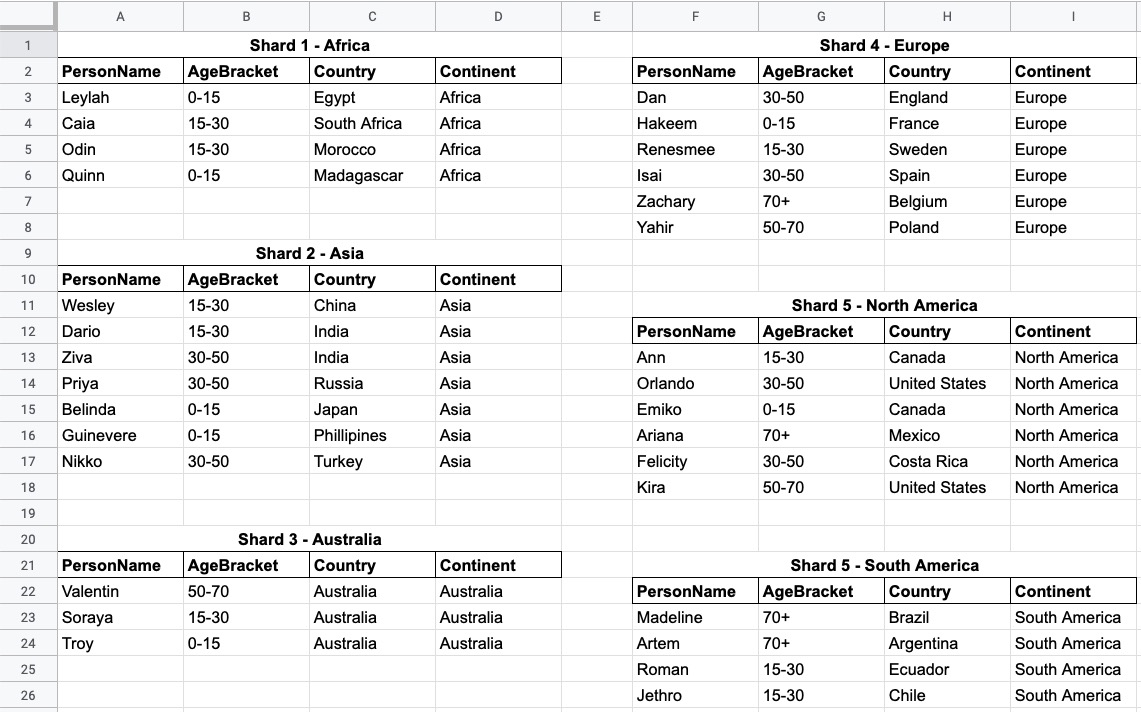
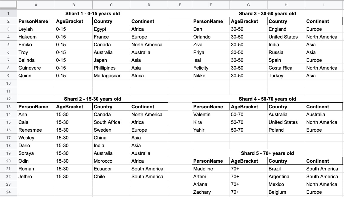
The concept of sharding in the property graph model takes on a slightly different approach than with other database models, which we will discuss next.
Graph data sharding and how it’s different
Sharding implementation is very much related to the type of database – graph, relational, key/value, document, and more. Another factor involved is data connectedness - the more data is connected, the more complicated it is to shard. Some sort of data redundancy is needed to bridge connections across shards and point to the connected entities. As you might imagine, this is a tricky thing to do for a graph database, which places high value on relationships in the data.
What is Neo4j Fabric?
Neo4j Fabric is Neo4j’s solution to graph sharding by allowing users to break a larger graph down into individual, smaller graphs and store them in separate databases. For graphs that are highly-connected, this means some level of data redundancy to maintain the relationships between entities.
As an example, NodeA and NodeB connected by RELATIONSHIP_1 could be sharded this way.
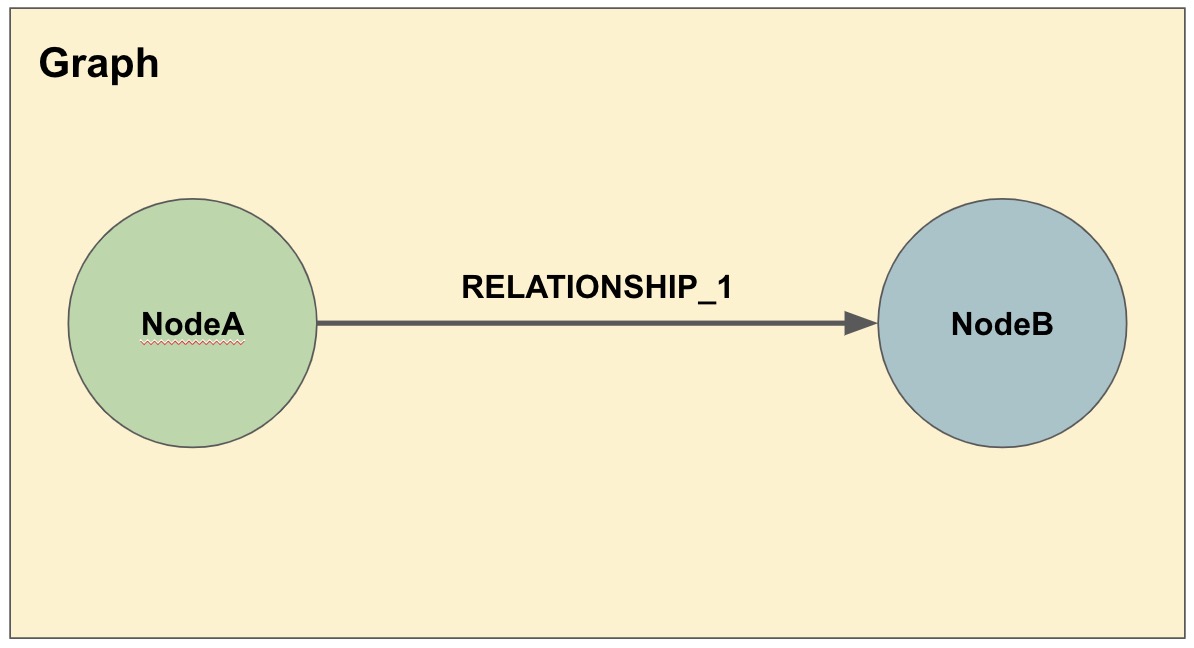
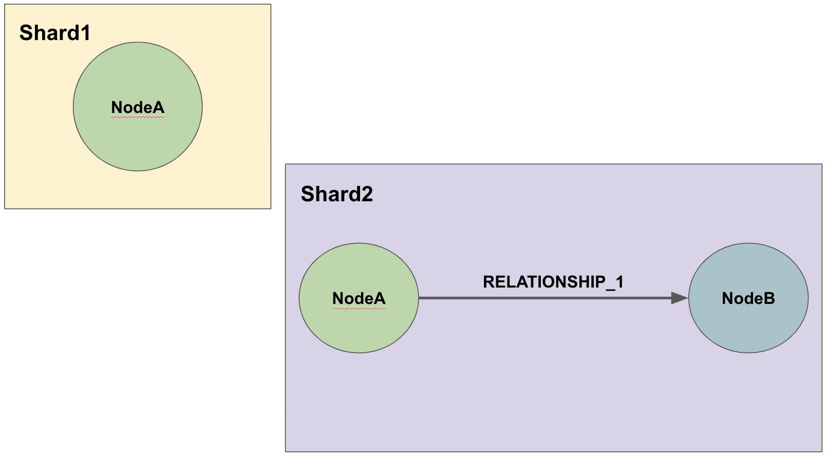
In the second diagram, we have decided that we will keep all of the NodeA nodes in one shard and then place the relationships from NodeA nodes to NodeB nodes in another shard.
The NodeA node shown in Shard1 and Shard2 are the exact same entity but duplicated into the second shard to store the relationship to it.
We can take our graph from the first diagram and move the data to the appropriate shard.
Then, when we run queries, Fabric will find the NodeA nodes we are interested in on one shard and pull the relationships from the other shard and bring that data together in results to send back.
Fabric structure
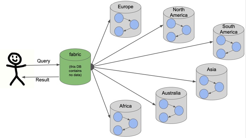
Neo4j sharding contains all of the fabric graphs (instances or databases) that are managed by a coordinating fabric database. The fabric database is actually a virtual database that cannot store data, but acts as the entrypoint into the rest of the graphs. We can think of this like a proxy server that handles requests and connection information. It helps distribute load and sends requests to the appropriate endpoint.
If we take our example from above with people data, we can visualize this structure. We will have 1 fabric graph that will manage all the connections and requests to the rest of the graphs. Then, depending on how we shard the data, we can have as many fabric graphs as we choose. For this example, we will shard the data by continent and create a separate database for each continent. Let us see what our system would look like with this model.

Queries coming from users or applications will hit the fabric database first, then get routed to the instance or instances required to answer the query. The answers from each involved graph are sent back to the fabric database, where they are aggregated or filtered into a unified result that is sent back to the requesting party. An example of this process is shown below.
Architecting a system with Fabric
There are a variety of ways to architect the people data sharded graph system, especially with capabilities for multi-database and clustering. Any or all of the graphs could be in the same DBMS on a physical server in a regional location, or graphs could be distributed across different DBMSs in physical and cloud servers around the world.
This can feel rather mind-bending, especially if you are new to the concept of sharding, so we will cover only 3 architectures (out of numerous options) that can be the choices for many scenarios.
Example 1: A single DBMS for everything
In this example, we will place all of our data into a single Neo4j DBMS. This DBMS could be hosted locally or remotely and on in-house or cloud servers. No matter the location of the DBMS, we have sharded our data into 1 instance for the fabric database and 6 separate instances for each of continents containing their people data.

Reasons for architecting the system this way is that there is a manageable amount of traffic for a single DBMS to handle, that latency has little to no effect on requests (coming from a narrow region set or not critical), or that there are no regulatory or data privacy issues with storing the domain together.
Example 2: Fabric database in separate DBMS
We can take our previous example up a level by placing the fabric database in a separate DBMS. Now, either our proxy (fabric db) or the data instances (people data) can be local or remote, in-house or cloud. Those choices depend on the requirements and preferences of necessary parties. We still have our shards categorized into 1 for the fabric database and 6 separate instances for the people data by continent.
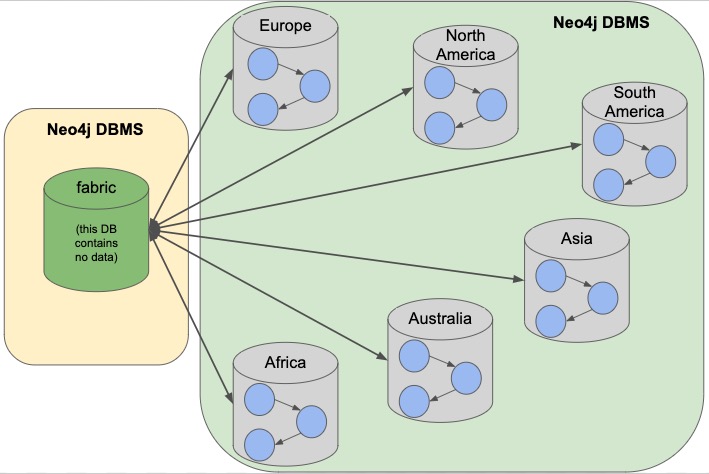
The reasons we might choose this architecture is that we need to load-balance the requests. To do that, we need to replicate the data across regions. Fabric databases must be standalone, single instances, though. By putting that instance into its own DBMS, we can then place all of the data instances into another DBMS that can be added to a cluster for replication. We could also replicate fabric’s single instance to manage more load to the clusters.
Example 3: Multiple DBMSs
One step further puts us separating the data stores into shards, as well, and placing certain ones into their own DBMSs. Any combination of local or remote, in-house or cloud can be used for each DBMS to fit business needs and requirements. The shards are still organized into 1 for the coordinator (fabric db) and 6 instances for the people data based on continent, but the change is that all of these instances are now bundled or separated into different systems.

This architecture might be chosen because certain data might be required to be hosted privately or separately from other data or because a bulk of requests are for a particular dataset. It could also be for reduced latency in requests to and from certain regions. Other requirements could also be solved with this particular setup.
In our particular example, we have done a combination of all of these. We have separated the fabric database to solely handle all of the load and processing of requests. Next, the Europe graph has been placed in its own DBMS for data privacy reasons to meet GDPR compliance for European user data. To the right of that, our North America and South America graphs have been placed in another DBMS to be hosted regionally, and our last DBMS for Africa, Australia, and Asia has been combined for region and load. Just as in our Example 2, we could replicate any or all of these DBMSs - fabric database with a second DBMS copy and any of the data DBMS into clusters for replication and load.
Other possibilities
Above, we only covered 3 example architectures and their common use cases. When we start discussing clustering, especially for certain DBMSs and not for others, it can start to feel complex and confusing. The same complexity exists around physically hosting in-house or remotely hosting in the cloud, as certain DBMSs might require one or the other. These two designs can also be combined where certain ones are hosted in-house, others in the cloud and some are clustered and replicated while others are not. As mentioned above, the fabric database can also be replicated (as a single instance) to provide more proxies for handling request load.
More examples on Fabric deployments can be found in the documentation section.
Implementation considerations
As mentioned earlier, the property graph data model required a specific approach to sharding compared to other data structures. The property graph model relies on nodes and the physical connections between them in order to create a graph. To implement sharding meant handling and managing that connected unit as many graph pieces and still retaining the value of the relationships across instances and clusters, along with maintaining data consistency and integrity.
There are a couple of specific things to consider for those looking to implement Neo4j Fabric. Other considerations are listed in the documentation.
Where to divide the data
The business or individual will need to make the decisions on data separation and manually refactor the data into shards for Fabric to manage. Determining the best places to divide the graph data into separate graphs for Fabric can be trickier than you might imagine, especially if the data is tightly connected. The best approach is to look for clean breaks in the data where there are few or no relationships crossing graphs. We can think of these as natural subgraphs or disconnected structures in our data where there is the cleanest division.
In our people data example, there are natural, clean divisions in the data by continent. We can split our data into people who all share the same continent, which means that there should be few to no people who exist in other continents.
The only exception to this is if our continent is based on citizenship/residence, as it’s possible (though unlikely) that many people will have citizenship in multiple continents. If so, we may need to have minimal duplication for this where the person’s data exists in each of the continents they are citizens. If our continent data is based on birth, however, it eliminates this, as a person cannot be born in more than one continent.
Understanding the context and data definitions, then, could also be important to making the best decision on where to divide the data. Another perspective to this is how the data is modeled, as this can impact whether clear subgraphs in the data naturally occur based on the model. We will look at this consideration next.
Data model/schema
The data model plays an important role in how Fabric is implemented and architected and how the data is divided. In a Fabric system, the data model can have even more impact on queries and performance, since we could be dealing with a variety of factors for latency, distance, breadth of query (how many shards does it touch), volume of requests to the Fabric database, and more.
Dividing the data as cleanly as possible is key to determine the number of databases involved and how much data will reside on each. Once that step is complete, we can begin organizing the instances into a combined or separate DBMS and determine replication needs.
Our people data example has a data model that fits our needs for dividing and querying the data. Whether we need to divide the data by continent or age bracket, we can do so and not end up with too many subgraphs (5 for age brackets and 6 for continents), and separating instances for privacy or replication also works well. As an alternative, separating by first letter of name could mean we end up with 26 (or more in non-English alphabets) potential databases or separating by country could mean around 200 potential databases (imagine if we needed to replicate these!). However, if working with billions or more entities, then 26 or 200 databases might be more valuable and efficient for many queries that only require a subset of the data.
Knowing ahead of time the types of queries that will be necessary of the systems or the kinds of requests that are most common will also help plan a data model that best suits the performance requirements of those queries and optimize for them. Our next paragraphs will take a closer look at this.
Query structure and optimization
Planning ahead by understanding the query requirements will help in constructing a data model and architecture that best optimizes for those expected requests. We cannot always plan every request that may be asked of the system, but drafting up those example queries we know can make a big difference in building a system that is designed to handle what is needed.
For our people data example, we have architected a system that can fit all of our query and performance needs. Using Example 3 with multiple DBMSs, perhaps we know that users will request information for both North America and South America in queries, so it makes sense to place both of those instances close together or in the same DBMS. Likewise, if queries for Australia will be very few, we can place that instance together with other instances to spread the load more evenly across DBMSs. Our Europe graph may get the bulk of the requests, so placing it in its own DBMS could help balance the load and avoid irrelevant traffic to that DBMS. Requirements may be completely different in your system architecture and may need a different structure.
The combination of all of these factors discussed will help improve stability and resiliency in handling business and data needs.
Resources
-
Documentation: Neo4j Fabric
-
Developer guide: Multi-tenancy Example with Multi-database and Fabric
-
Blog post: Adam Cowley on Neo4j Fabric
Was this page helpful?